4-Metre Band 5/8 Wave Vertical Antenna
Introduction
 This project began after a friend (Graham
M0GDE) found me a Phillips
FM1100 PMR radio suitable for conversion to the 4-m band. I
carried out the PA4DEN conversion procedure and then found myself in
need of an antenna with which to test and use the rig.
 I first tried a folded-J made from 300 ohm feeder, but without much success.
I had a CB-style steel whip antenna element with a 3/8 inch screw fitting at the base (courtesy of my local emporium), and the length was just about right for a 5/8 wave design on 4 metres. This appealed as it would offer substantial gain and lower angle of radiation compared to a simple quarter-wave ground-plane, and it seemed simpler to construct than a folded J.
The project has taken a while to appear in hardware form because of time spent in designing, producing drawings and then finding someone prepared to produce the parts in small quantities at a reasonable (!) cost.
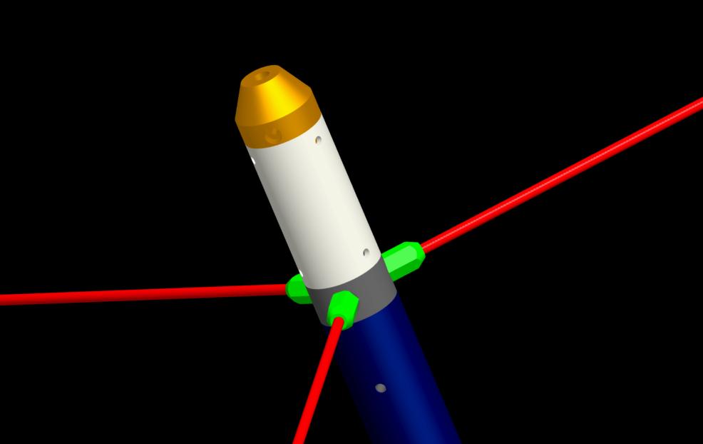
The picture shows a prototype (complete with red insulating tape on the joins) being tested atop a small mast. For scale, the base of the antenna is about 40 mm in diameter, the radials are about 1m long and the radiating element is about 2.4m long.
5/8 Wave Antenna Theory
This is a vertical, end-fed ground-plane antenna that incorporates radial elements (3 in my case).Radiation Pattern and Gain
The principal reasons for selecting the 5/8 wave length are the increased collection aperure compared to a quarter- or half-wave antenna, and the strong low-angle radiation lobe which offers potentially high gain. These proprties come from the length of the radiating element and its mounting position over a ground plane.Various references (including the ARRL Antenna Handbook) show the calculated ideal radiation patterns form a simple linear radiating element as its length is increased. When the length is equal to half a wavelength, the familiar "doughnut" radiation pattern obtains, with maximum radiation orthogonal to the radiating element and a gain of about 2.15 dB relative to an idealised isotropic (non-directional) radiator. As the length is increased the radiation pattern tends to become asymmetric with elevation angle and to develop multiple "lobes" and nulls. It is found that a 5/8 wave element driven against a ground plane (so that it induces a virtual "mirror" radiator below the ground plane) posesses a partiicularly strong lobe at a relatively low angle of radiation (around 16 degrees). The calculated gain with respect to a half-wave dipole is approximately 1.5 dB, and the strongest radiation lobe is angled closer to the horizontal than would be the case for a half-wave or quarter wave antenna fed over a ground plane. Further increases in radiator length produce more lobes and the gain drops.
Impedance Match Strategy
Having selected the desired gain, the geometry of the antenna is fixed:
one is now faced with the separate (though related) task of matching
the antenna to its feeder. For convenience of mounting,
end-feeding is preferred.The first point to realise is that the 5/8-wave antenna is not self-resonant (5/8 is not an integer multiple of 1/4) so a signal or wave travelling from one end to the other and back will not return in-phase with the driving signal. In fact, the end of the antenna presents a capacitive reactance at its operating frequency (i.e signals return with a phase lag of about 90 degrees).
In order to build up a substantial current in the antenna, it is usual to resonate it: this can be done by adding a series inductance at the antenna base connected to ground to form a series L-C resonant circuit (sometimes called a "trap" circuit"). A suitable match to a typical coaxial feeder can then be obtained by tapping into this inductance at an appropriate point above the ground connection.
There is an alternative method which is a little simpler to construct (it avoids tapping the coil). It is observed that a 3/4-wave antenna (which does not have such a nice radiation pattern) happens to exhibit an end-feed impedance very close to 50 ohms. Such an antenna presents a good match to typical coaxial cables. The 5/8-wave element may thus be matched by making it appear electrically but not physically equivalent to a 3/4-wave element. This is achieved in practice by adding a series inductance which approximates 1/8-wave of conductor coiled up so that it does not radiate significantly. The coaxial cable is then attached directly to the bottom of the coil.
The design presented herein adopts the un-tapped series inductor approach to matching, Results from the prototype are presented below.
Physical Design

The antenna base (grey) is designed to fit inside the top of a standard 1.5 inch aluminium tubular mast (shown in dark blue). The base has an RF connector (either SO239 or N-type) fitted: both the connector and the cable are protected from weather to some extent by the mast and the shielding effect also helps unwanted prevent radiating currents on the outside of the braid of the coaxial cable. The base supports three radials which are fabricated from rods cut to about a quarter-wavelength at mid-band. The design calls for hexagonal sections to be brazed on to aid in tightening and retaining the radials.
The base section also supports two co-axial glass-reinforced composite tubes: the inner tube serves as a coil former and provides some mechanical support whilst the outer tube (shown in white) acts as the main mechanical support and also as a weather shield. There is sufficient space to fit a coil made from 3 mm or 1/8 inch diameter copper wire or microbore tube: this is intended as a way of minimising RF losses from the skin effect.
The top section (gold) has a 3/8-inch tapped hole in the top that accepts the threaded base of the whip antenna element (or any other element with that fitting). It also has an axial hole and grub screw arrangement that accepts and clamps the wire coming from the top of the coil.
The prototype design model shows screw holes for joining the parts, but a final design would probably use adhesive and sealant for a more permanent assembly.
Materials Selection
Stainless steel (316) has been selected for the antenna base, radials and top caps; it does not have the conductivity of aluminium, and is much heavier, but it is relatively cheap, highly robust, resistant to corrosion, and cheaper / easier to machine than titanium. The resistive losses were thought to be acceptable.The radiating element in this case is a very flexible and tempered grade of stainless steel (unknown alloy), although it too could have been manufactured from 316 alloy rod. The resistance of this element is relatively high so some loss is expected; its small (tapering) diameter is expected to give a relatively narrow bandwidth antenna. On a positive note, the element is extremely flexible and unlikely to be damaged by wind.
The insulating sections (coil support and outer support / weather protection) are made from high-quality glass-reinforced resin composite "pultruded" tube. This material has very good strength and toughness (essential qualities when supporting such a long antenna in high winds.
There is a potential for some corrosion of the aluminium alloy mast if the junction with the stainless steel base becomes wet (250 mV difference in electrochemical potential). In practice this is not likely to be serious and can be remedied by anodising, aluchroming or painting the aluminium mast section.
Testing
The antenna was mounted on a telescopic mast and raised well clear of buildings to about 4m above ground. For reference measurements, an identical assembly was constructed with the matching coil replaced by a straight length of wire.Measurements of impedance seen at the base of the antenna were made using a Vector Network Analyser (VNA): the unit used was a "Mini-VNA" which is available from my local emporium. The Mini-VNA is a very versatile and useful piece of kit: in this case it permits complex impedance (resistance and reactance with the correct sign) to be measured at a series of frequencies within a desired range. In combination with an excellent piece of software called "ZPlots", the results can be graphed and even represented on a Smith chart. The Smith chart gives a particularly clear way to visualise how the matching process operates.
Measurements were made using a short length of coaxial cable the electrical effects of which (loss and phase shift) were allowed for in the software.

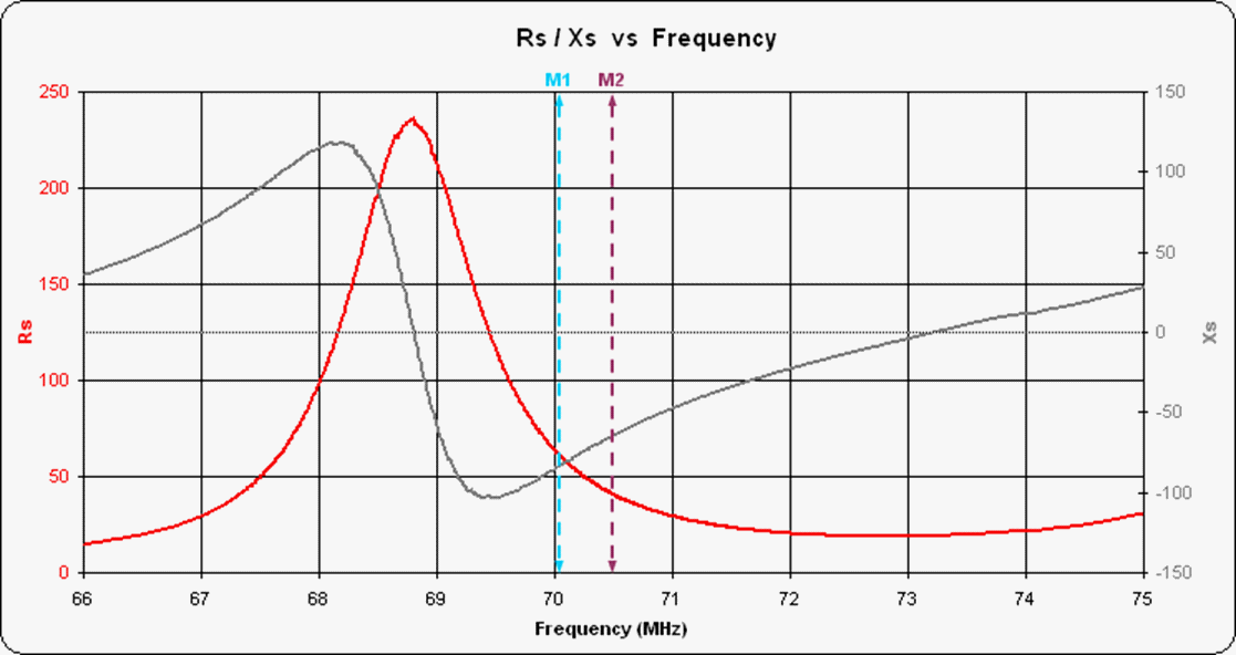
The un-matched antenna shows a resistive impedance (left-hand vertical axis) that is close to 50 Ohms within the 4m band (shown approximately by the two markers M1 and M2) but it has a large capacitive reactance (capacitive because the sign is negative, indicating a phase lag). The overall impedance is approximately 50 - j75 Ohms in the band centre. This is roughly in line with expectations. It is worth bearing in mind that the measurements include the effects of the quarter-wave radials which are cut to be resonant in the 4 metre band but which will not provide a "solid" groundplane at other frequencies!

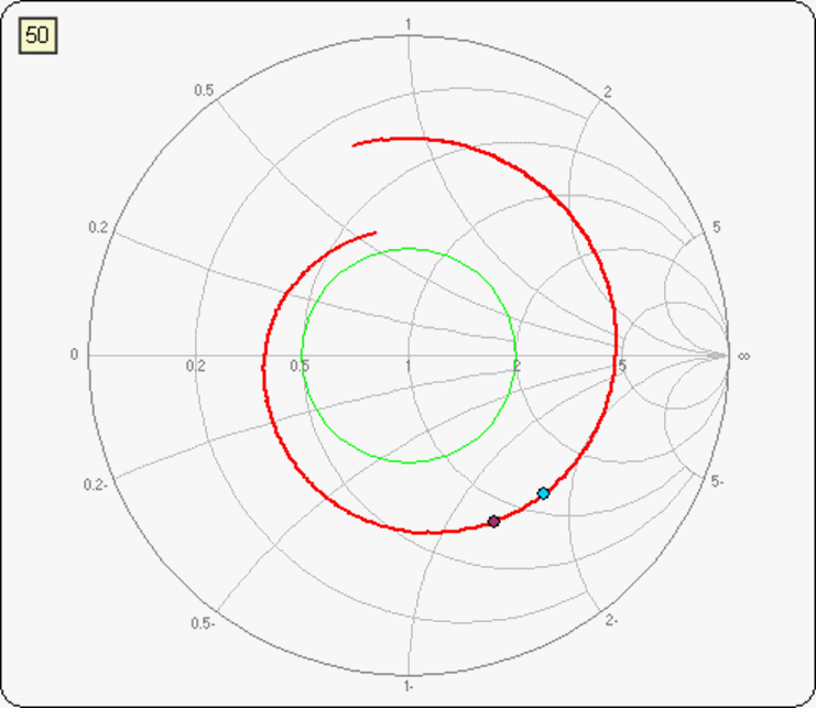
The same data were plotted on a 50-Ohm impedance-type Smith chart (above) with the markers set at either side of the 4 metre band. The target impedance (50 Ohms) is located at the centre of the plot (labelled "1"). The horizontal axis represents resistance in multiples of 50 Ohms, running from short circuit on the left to open circuit on the right. Reactance is represented by a deviation below (capacitive) or above (inductive) the central axis. The circle-segments which appear to emerge from the extreme right and cut the outer edge of the plot are lines of constant reactance (with values normalised to 50 Ohms). The circles which are all tangent to the right-hand side are lines of constant resistance: the circle that passes through the centre of the plot marks all points whose resistance is 50 Ohms (only one of which - the centre point - is purely resistive).
For example, consider a frequency in the middle of the 4m band (between the markers). The conventional plot shows that the resistance is about 50 Ohms, and the two markers "straddle" the 50 Ohm circle on the Smith chart. The reactance in the middle of the band is approximately -75 Ohms, which is equivalent to -1.5 times the target impedance of 50 Ohms. The two markers sit mid-way between two circles of constant normalised reactance labelled "1-" (equivalent to -50 Ohms) and "2-" (equivalent to -100 Ohms).
If any measured impedance plots inside the green circle on this Smith chart, the SWR will be less than 2:1. The closer the impedance at the frequency of interest can be brought to the centre point, the better the match.
To match the antenna it is necessary to insert a series inductance whose positive reactance cancels the negative capacitive reactance of the antenna without affecting the apparent resistance.

On a Smith chart, a series inductance moves a point along a circle of constant resistance by an amount determined by its inductive reactance (which varies with frequency!). The second Smith chart shows how the points defined by the two markers have been moved almost to the centre of the diagram. The match is not quite perfect: there is still a slight capaciticve reactance across the band and the resistance has crept up slightly, possibly due to losses in the coil (although the coil was substantial in this case!). The worst match occurs at the lower end of the band (light blue marker) whilst the match at the upper (FM) end is very good. (The small discontinuities result from problems measuring the phase accurately - the trace should resemble a smooth loop!)
Note that the other, out-of-band, impedances have also been affected by the series inductance. They have all been moved around circles of constant resistance by differing amounts as the inductive reactance varies with frequency. The result is that the impedance plot has been "looped" near the 50 Ohm point. This antenna would therefore offer a reasonable match over quite a wide band of frequencies.
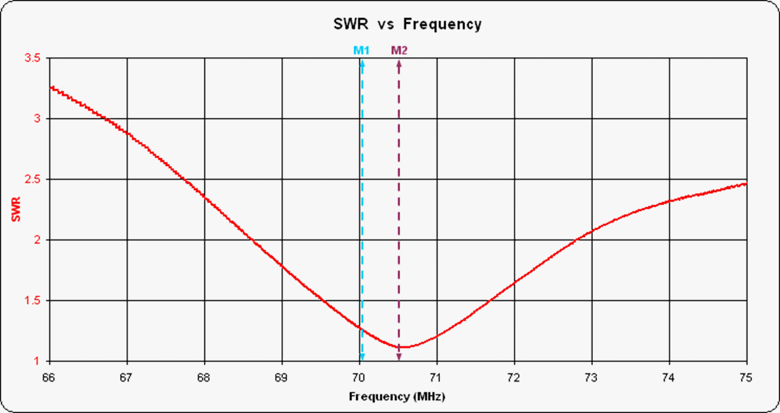
The impedances can be used to calculate the SWR to give a more conventional if over-simple view of the matching process.

As noted, the best match occurs around the top of the band - slighty more inductance is required to move the minimum SWR towards the middle of the band. The SWR does not reach 1 because the resistance has crept up just a little and the reactance was not quite fully cancelled out.
Note that it might be possible to improve the bandwidth somewhat by using a larger-diameter radiating element: the thin, tapered vehicle whip is expected to give quite a narrow bandwidth.
Testing
The antenna has been tested "on-air" using the "Parrot" (MB7FM) located
near Tring (at a distance of about 53 km). The antenna was sited
near Kingston in Surrey (my home QTH) and raised to about 5 m above
ground level clear of buildings. The feeder was about 25 m of
RG213 co-axial cable and the exciter was a converted FM1100 PMR radio
with its front-end filters optimised in the 4 metre band (which does
make quite a difference!). Using a power of about 25 Watts, the
"Parrot" receives and repeats my signal with smooth noise and good
readability. This is not a definitive test of
performace of course, but in the absence of proper gain measurements
it does show that the antenna is useable!Conclusions
There is no new material in this project: the design and matching of 5/8-wave antennae is quite well known.The project has taught me several practical lessons, both regarding practical matching and also practical aspects of design and construction. The result has been a practical prototype antenna which will now be subjected to life testing and further tweaks, and from which may come a more easily constructed "production" version.
This page is under construction. More details will be added concerning the construction, adjustments and assembly of the antenna and the evolution of the prototype.